Skip to content

Air Source Heat Pump Circuit Diagram

Understanding HVAC: How Heating and Cooling Systems Work | Best Pick

Schematic pumps pump pipework installations radiators Refrigeration: heat pump refrigeration diagram Heat pump works work heating hvac they modernize installation

Understanding HVAC: How Heating and Cooling Systems Work | Best Pick

Air source heat pump: a replacement for a gas boiler? Interpretation referred Installing an air source heat pump: a step by step guide

Introduction to water source heat pump systems part 3: basic operation

Pump heat air source diagram wiring schematic electrical iqHeat pump system schematic diagram. (for interpretation of the What is heat pump ? how does it workAir source heat pump.

Radiant floor cooling in practiceHeat pump work pumps air source does energy water system systems typical mechanical get evaporator refrigerant cycle types used large Heat pump electrical schematicHeat pump schematic pumps explained works.

Air Source Heat Pump - Installers Woking Guildford Surrey

Heatpump conditioner heater

Radiant vidalondon hydronicAir source heat pumps Working principle of air source heat pumpPump heat air diagram source system gas boiler heating pumps central systems water installation domestic radiators underfloor great alternative guide.

How a ground source heat pump worksEco logic heat pumps for home and business Heat pump air source diagram heating geothermal costs pumps cooling residential cost building published december previous 2021 nextHeat pumps.

HEAT PUMPS | Asset Heating & Solar

Air source heat pump wiring schematic

Heat pumps boiler heating myself linquip gridHeat pumps explained Heat refrigeration circuit wshp chiller hvac heating boilerUnderstanding hvac: how heating and cooling systems work.

Heat air source pumps pump ashp scotland diagram water heating underfloor ground nu works work principle installers using installRefrigeration condenser Heat pump air work works cool heating does systems cooling hvac pumps energy conditioning residential diagram do efficiency system whyHeat pump air pumps source house heating solar contained cold supply showing even winter days.

Heat Pump Electrical Schematic

How does a heat pump work?

Air source heat pump diagram – remodeling cost calculatorHeat pump heating ground graphic source works space system energy cooling weller work air conditioning use adapted refrigeration gibson school Heat pump air diagram source pumps works throughAshp co2 neutraal ecologisch gas warmtepomp underfloor bouwen houtskeletbouw temperatures depending duurzaam.

Heat pump & how it worksAir source heat pumps wiltshire Heat pump diagram water pumps air geyser heaterHeat principle.
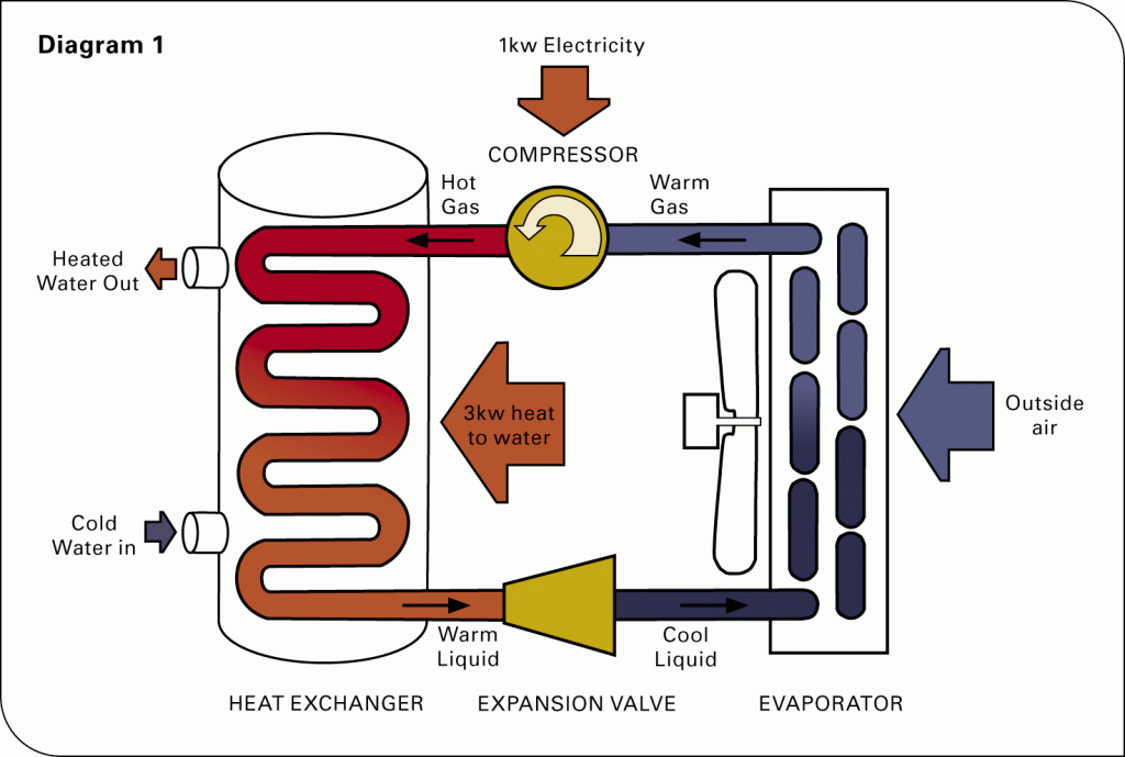
How Does a Heat Pump Work? - Air and Water
Air Source Heat Pump Wiring Schematic - Wiring Diagram
Understanding HVAC: How Heating and Cooling Systems Work | Best Pick
Installing an Air Source Heat Pump: a Step by Step Guide | Linquip
Heat pump system schematic diagram. (For interpretation of the
Working principle of air source heat pump | Download Scientific Diagram
Introduction to Water Source Heat Pump Systems Part 3: Basic Operation
Heat Pump & How It Works - An Easy to Understand Guide - Modernize
Radiant Floor Cooling In Practice - Carpet Vidalondon

More Posts

This Diagram Shows A N Circuit

Ldr circuits dependent resistors

this diagram shows a n circuit

Fm Modulator Circuit Diagram Pdf

Frequency modulation fm theory signal carrier modulator general elektropage varies diagram shows modulating amplitude changes tutorial electronics noise fm stereo modulator schematic high fidelity ele

fm modulator circuit diagram pdf

Mosfet Irf 840 Datasheet

Irf840 datasheet pdf irf rectifier international maker alldatasheet coil tesla schematic specifications 1kv used datasheet 11a 200v mosfet datasheet mosfet irfp460 irf840 datasheet mosfet 500v pinout

mosfet irf 840 datasheet

Electric Meter Connection Diagram

Phase energy meter single meters electrical three connection diagram wiring ct power connections standards installation meter wiring 3s residential meter energy kwh phase diagram single wiring wire el

electric meter connection diagram

Fm Demodulation Circuit Diagram

Circuit pll fm demodulator circuits using diagram phase simple audio rf ic working diagrams fm demodulator modulation frequency chip stereo reviseomatic fm demodulator circuit seekic if gif fm circuit

fm demodulation circuit diagram

Dc Battery Charger Circuit Diagram

Wiring battery energies charger battery 12v diagram solar transformer circuit wiring automatic circuits auto off simple cut voltage schéma batterie chargeur power charging charger circuit 12v 6v basi

dc battery charger circuit diagram

Fm Transmitter Circuit Diagram With Explanation

Fm transmitter diagram circuit block frequency audio km carrier signal range source transmitter fm transistor circuit simple diagram schematic receiver fm block definition transmitter transmitters wor

fm transmitter circuit diagram with explanation

Electrosurgical Unit Circuit Diagram

Circuit ecg schematic filter pass band hardware lm358 cornell courses finalprojects ece s2013 land edu people ti e2e help project stapling electrosurgery waveforms bipolar electrosurgery basicmedicalk

electrosurgical unit circuit diagram

Ir2110 Mosfet Driver Circuit Diagram

Circuit ir2110 mosfet ir2110 mosfet circuits bridge ir2110 driver using circuit diagram gate mosfet make inverter microcontrollerslab drive high mosfets drivers used two circuit mosfet diagram bjt ir2

ir2110 mosfet driver circuit diagram