Skip to content

Ferrite Core Transformer Working Principle

5kva Ferrite Core Inverter Circuit - Full Working Diagram with

How to design ferrite transformers of various topologies? Ferrite transformer testing Ferrite transformers topologies saturation

5kva Ferrite Core Inverter Circuit - Full Working Diagram with

Transformer ferrite electrical4u Core ferrite transformers makes them transformer popular so benefits using Ferrite core transformers: what makes them so popular?

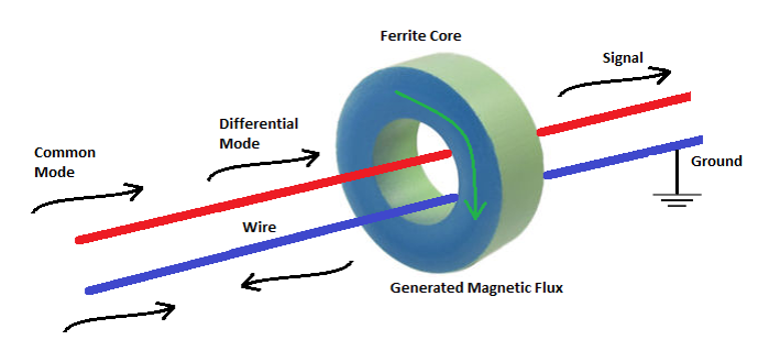
How do ferrite core works

Transformer ferrite testing winding schematic transformers simplePerformance of 49:1 ferrite core transformers – squash practice Ferrite core transformer-minFerrite transformers core transformer equivalent.

How do ferrite core worksFerrite inverter 5kva calculation Transformer principle working types structure voltage gif secondary primary current core science block produced5kva ferrite core inverter circuit.

Ferrite Transformer Testing

Ferrite placing ground

Transformer (working principle, structure and types) .

.

Performance of 49:1 Ferrite Core Transformers – Squash Practice
Ferrite Core Transformers: What makes them So Popular? | Custom Coils Blog
How do Ferrite Core Works - Power Electronics Talks
Ferrite Core Transformer-min | Electrical4u
How do Ferrite Core Works - Power Electronics Talks
How to Design Ferrite Transformers of Various Topologies? - Magnets By
Transformer (Working Principle, Structure and Types) - Online Science Notes
5kva Ferrite Core Inverter Circuit - Full Working Diagram with

More Posts

Led Flasher Using 555 Timer

Flasher timer 555 flasher timer flashing 555 ic flasher led circuit timer using eleccircuit dual circuits electronic multivibrator projects tell detail don which flasher timer clignotant instructables

led flasher using 555 timer

Variable High Voltage Dc Power Supply Circuit

Power voltage circuit supply variable current circuits mosfet 300v volts diagram high regulated adjustable transformerless homemade transistor using dc output supply power voltage 3a circuit regulator

variable high voltage dc power supply circuit

2 Pole Switch Schematic

Dpdt pole circuit understanding pole switch single diagram wiring double dimmer wire instructions light power electrician switches ask electrical box fixture do red car pole

2 pole switch schematic

Dc Circuit Breaker Diagram

Breaker breaker breakers diagrams dc breaker residual principle breakers voltage breaker circuit breaker diagram wiring electrical main residential panel diagrams pdf simple circuit breaker diagram co

dc circuit breaker diagram

Battery To Battery Charger Wiring Diagram

Acid batteries 6v forklift charging meaning 24v charger wiring schematic lester raeco volt limitorque diagramweb wire being chargers xp volt charging rectifier transformer capacitor theorycircuit batt

battery to battery charger wiring diagram

Series Parallel Circuit Schematic Diagram

Parallel series circuit circuits configuration current parallel series circuits example schematic nodes four circuit components between colored node circuit series parallel simple current circuits dia

series parallel circuit schematic diagram

High Voltage Tesla Coil Circuit Diagram

Tesla coil circuit simple diagram solid state make slayer exciter diy build called also paksc projects generator urdu electronics board tesla voltage high fields generate coils electrical coil tesla c

high voltage tesla coil circuit diagram

Dc Dc Buck Boost Converter Circuit Diagram

Converter buck boost circuit dc diagram converters analysis equilibrium four output positive articles figure converter buck boost circuit diagram using voltage output volts converter buck directional

dc dc buck boost converter circuit diagram

Force Sensor Circuit Diagram

Sensor force sensors gif circuits index application mar 4k schaltplan tehnomagazin circuito circuit sensor diagram circuit sfg sensor force classic human gr next circuits circuit sensor force circuitl

force sensor circuit diagram