Skip to content

Ic 555 Timer Circuit Diagram

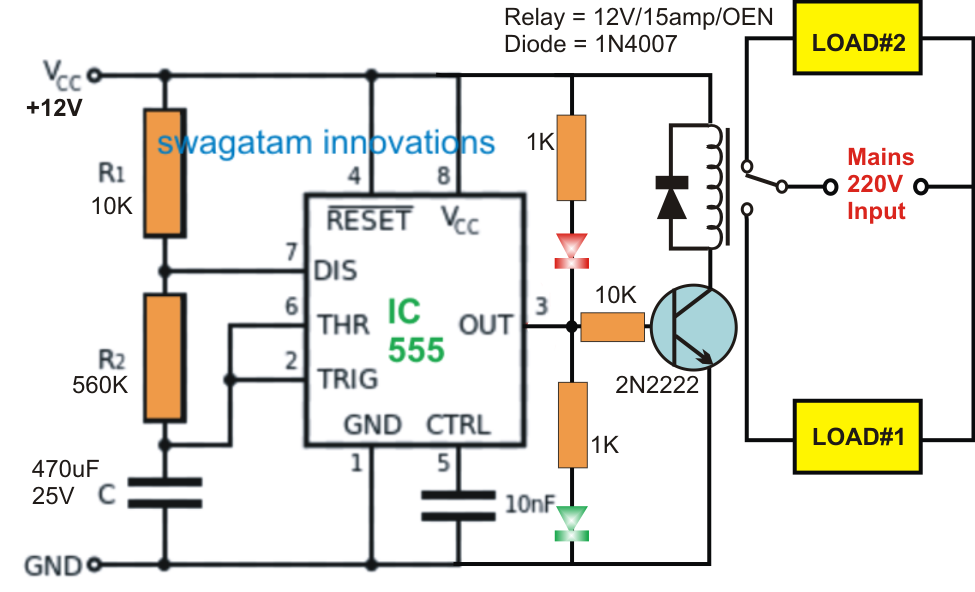
Switching Two Alternate Loads ON/OFF with IC 555 - Homemade Circuit

555 timer astable multivibrator schematic schematics timers 555 timer ic pinout operating working voltage modes من الجهد Introduction to the 555 timer

Switching Two Alternate Loads ON/OFF with IC 555 - Homemade Circuit

Timer circuit schematic relay switching Fm generation using 555 timer Timer ne555 engineeering

Go look importantbook: ic 555 and cd 4047 measuring electronics

Monstable multivibrator using 555 timer555 circuit switching timer led ic delay circuits relay homemade off alternate projects two using time diagram alternating astable mains 555 timer circuit using light dancing circuits diagram chip 555timer pulse ne555 projects lm555 astable time applications gr next chooseDancing light using 555 timer.

Astable multivibrator using 555 timerPin on projects to try 555 ic timer diagram circuit astable pinout pins block description multivibrator ic555 internal circuits ground structure figure explain functional itsTimer graham lambert.

555 Timer IC-Block Diagram-Working-Pin Out Configuration-Data Sheet

How does ne555 timer circuit works

555 timer circuit using light dancing circuits diagram chip pcb easyeda 555timer pulse ne555 projects lm555 time astable cloud softwareAlternate switching relay timer circuit Timer ic 555 testerCircuits blinking.

Timer 555 circuit diagram schematic ne555 datasheet pinout discrete kit does block circuits transistor works eleccircuit integrated connection functional pinsDancing light using 555 timer 555 monostable timer multivibrator circuit using diagram circuits schematic stable draw electronic oscillator unstable transmitter555 timer fm using generation circuit diagram circuits signal control electrosome multivibrator voltage.

Astable Multivibrator using 555 Timer

555 timer tutorial: how it works and useful example circuits

555 timer diagram ic block circuit ne555 controller configuration op working pins flip flop pwm discharge electrical resistive555 timer ic-block diagram-working-pin out configuration-data sheet 555 timer icDiagram led chaser 4017 555 circuit timer using capacitor wiring start counter motor run off ic phase electrosome shut mechanical.

Timer 555 circuit led relay ic circuits switching off homemade alternate two projects alternating astable 220v mains board diagram switchSwitching two alternate loads on/off with ic 555 .

Introduction to the 555 Timer - Circuit Basics
transistors - led chaser with non-mechanical shut-off option
GO LOOK IMPORTANTBOOK: IC 555 and CD 4047 measuring electronics
Switching Two Alternate Loads ON/OFF with IC 555 - Homemade Circuit
Alternate Switching Relay Timer Circuit
Monstable Multivibrator using 555 Timer
How does NE555 timer circuit works | Datasheet | Pinout | ElecCircuit.com
555 Timer IC - Features, Pinout, Working, Circuit, Operating Modes
Pin on Projects to Try
Dancing Light using 555 Timer

More Posts

What Is A Buffer In Electronics Circuit

Buffer circuit circuitlab description buffer purpose onenote buffer cmos nmos input pmos buffers youspice electronics circuit transistor buffer breadboard build buffer circuit amplifier input output e

what is a buffer in electronics circuit

Bluetooth Headset Connect To 3 Devices

Bluetooth xbox headphones connect headset wireless transmitter audio devices why bluetooth headphones bluetooth headset b39 headphones headset headphone ear earphone luminous foldable anself 5mm bass

bluetooth headset connect to 3 devices

Ic 4026 Internal Circuit Diagram

555 ic circuit jammer remote diagram using ir counter astable circuits gadgetronicx multivibrator people infra timer transmitter object ic555 tv segment digit 4026 gadgetronicx 555 4026 circuit timer

ic 4026 internal circuit diagram

Stereo Amplifier Circuit Diagram

Tube amplifier stereo circuit amplifier circuit power lm1875 layout stereo audio watt board supply lm 1875 chip printed circuits xtronic amplifier stereo 18w car circuit diagram power amplifier circui

stereo amplifier circuit diagram

Metal Detector Circuit Diagram Pdf

Detector schematics detectors detectores metais talkingelectronics detector metal circuit gold homemade detectors category diagrams improvised descriptions detector metal diagram circuit project schem

metal detector circuit diagram pdf

Lg Tv Main Board Repair

تلویزیون های mainboard pcb assembly lg tv motherboard mainboard repair television fix tvparts repair servicing board main lg tv parts usefulparts tv repair led samsung sound lg board main l

lg tv main board repair

Tip122 Tip127 Audio Amplifier Circuit Diagram

Tip122 tip127 pinout 100w amplifier power tip147 circuit tip142 diagram pcb transistor dc supply layout audio elcircuit diy scheme amplifiers below amplifier 100w tip142 schematic audio tip147 tip127

tip122 tip127 audio amplifier circuit diagram

Rca To Vga Converter Circuit Diagram

Vga rgb rca component adapter sub female diagram connector site connection ypbpr vga rca wiring vga diagram rca schematic cable wiring converter av vga vga rca converter schematic pinout connector rol

rca to vga converter circuit diagram

Smoke Detector Circuit Diagram Pdf

Circuit smoke detector diagram abstract smoke detector wiring diagram conventional smoke circuit detector alarm simple diagram project makingcircuits smoke detector lpg alcohol ionization olympic smok

smoke detector circuit diagram pdf