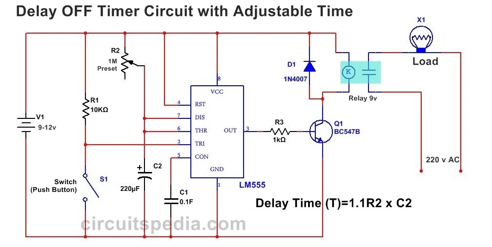
Off Delay Timer Circuit Diagram
Circuit for a few milliseconds time delay? Wiring diagram for 11 pin relays 555 delay off timer circuit for delay before turn off circuit
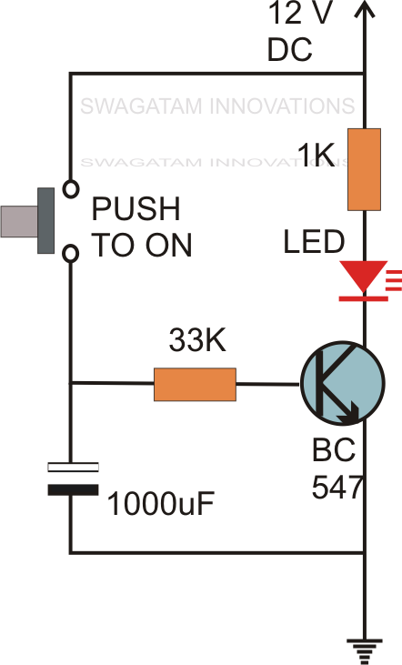
Adjustable Auto On Off Delay Timer Circuit Using 555 IC
On off timer relay circuit diagram Delay timer circuits circuit simple electronic explained diagram homemade seconds schematics electronics step two using make projects sequential few transistors Relay wiring delay timer timing connection electricalacademia
Simple delay timer circuits explained
Time delay relay using 555 timer, proteus simulation and pcb design555 delay timer circuit off diagram time circuits switch timers using simple make application display voltage electronics choose board lamp Delay closed normally relay nctc timingTimer delay adjustable circuit off 555 schematic ic using auto explanation works.
Timer delay eewebRelay diagram wiring delay timer off layout state solid base time socket connection relays control motor pins dayton contactor 120v Timer delay 555 circuit off using ic auto adjustable simple schematic relay module output dc inline loads appliances heavy acTimer delay relay 555 proteus circuit simulation.

Adjustable auto on off delay timer circuit using 555 ic
Time delay relayDelay timer circuit off 555 diagram switch time power turn circuits before given Adjustable auto on off delay timer circuit using 555 icCircuit delay timer simple circuits projects transistor time relay electronics explained electronic schematic homemade diagram power off diagrams electrical few.
555 timer delay off circuit diagramSimple delay timer circuits explained Solid state timerDelay timer circuits circuit simple electronic explained diagram seconds trigger electronics homemade step two schematics few projects sequential long.