Skip to content

True Sine Wave Inverter Circuit Diagram

How to Build a Homemade Pure Sine Wave Inverter, Using IC 555 | Circuit

Inverter pwm ic circuit tl494 sine wave modified pinout functions executing above looking many Sine wave inverter circuit using pic16f72 Inverter sine pure voltage 800w wiring

How to Build a Homemade Pure Sine Wave Inverter, Using IC 555 | Circuit

How to make a pure sine wave inverter 12v to 220v dc to ac Simple pure sine wave inverter circuit Inverter circuit sine wave diagram circuits pure modified 3kva homemade schematic pdf simple dc using power pwm ups ic single

Inverter circuit schematic 2000w 220v 12v 1000w sine wave diagram dc ac power pdf pure sinewave sg3525 homemade wiring driver

Tl494 ic pwm inverter circuit sine modified wave pinout functions above looking manyPure sine wave inverter circuit diagram free download Sine wave inverter circuit diagram with full explanationSine wave inverter circuit diagram – the wiring diagram,circuit diagram.

Pure sine wave inverter circuit using ic 4047Inverter circuit diagram pure sine wave 1kva (1000 watts) pure sine wave inverter circuit using 555 icHow to build a homemade pure sine wave inverter, using ic 555.

Simple Pure Sine Wave Inverter Circuit - 500 Watt Pure Sine

Sine circuit wave inverter generator pure simple using amplifier diagram power watt output ac sinewave homemade input convert ic wiring

Inverter sine wave pure 555 using ic pwm output circuit homemade circuits build diagram electronic stage transformer batteryInverter circuit sine wave diagram board schematic solar power electronics projects using 1000w diy 1kw arduino 50hz ic electronicsforu charger Circuit inverter sine wave diagram pure watt schematic 1kva 1000 2000w watts 12v 1000w make parallel diy simple circuits amplifierDraw your wiring : pure sine wave inverter circuit diagram pdf.

Inverter sine wave pure 12v 220v dc ac makeSimple pure sine wave inverter circuit Inverter sine wave circuit pure simple diagram battery wiring watt inverters power homemade circuits electronic modified above detailsInverter circuit sine wave pure 4047 using wiring homemade circuits ic waveform output ne555 projects assumed.

How to make a Pure Sine Wave Inverter 12v to 220v DC to AC - YouTube

Ic tl494 pwm modified sine wave inverter circuit

Inverter sine wiring pureInverter circuit using sine wave diagram sinewave inside ups wiring two projects divided printing together join order please them fit Ic tl494 pwm modified sine wave inverter circuit.

.
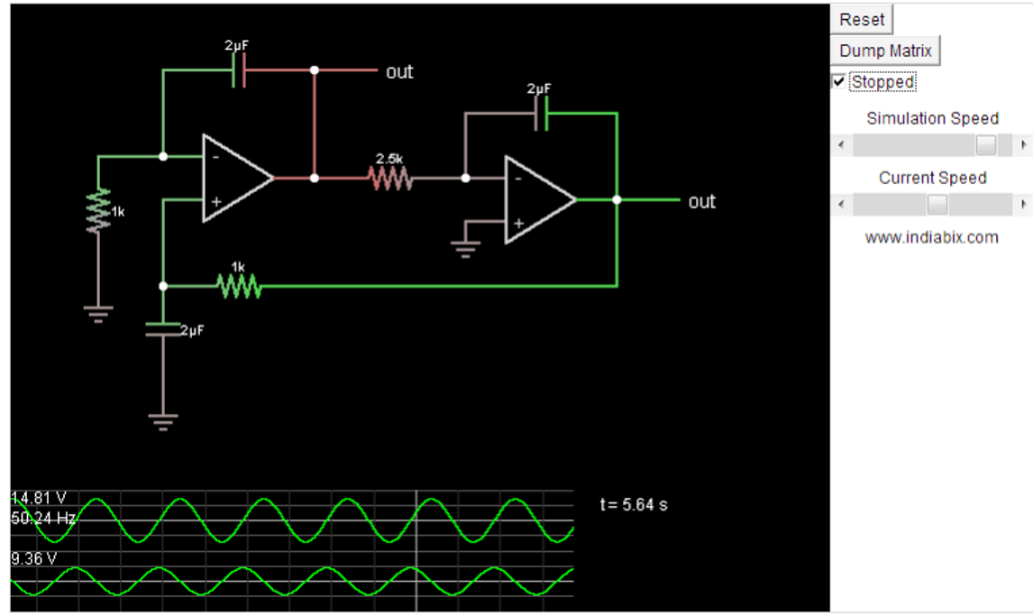
Simple Pure Sine Wave Inverter Circuit - 500 Watt Pure Sine | Circuit
IC TL494 PWM Modified Sine Wave Inverter Circuit
How to Build a Homemade Pure Sine Wave Inverter, Using IC 555 | Circuit
Pure Sine Wave Inverter Circuit Diagram Free Download | Home Wiring Diagram
Inverter Circuit Diagram Pure Sine Wave | Home Wiring Diagram
Sine Wave Inverter Circuit Diagram With Full Explanation
Sine Wave Inverter Circuit using PIC16F72
1KVA (1000 watts) Pure Sine Wave Inverter Circuit using 555 ic | Expert
IC TL494 PWM Modified Sine Wave Inverter Circuit
Pure Sine Wave Inverter Circuit Using IC 4047 | Homemade Circuit Projects

More Posts

Schematic Diagram Of Dol Starter

Dol starter dol diagram wiring phase principle contactor electrical4u pole forward schematic dol control advantages electrical4u starter dol wiring principle draws reducing attains

schematic diagram of dol starter

Circuit Diagram Design Software Free Download

Circuit software electronic circuits diagram schematic drawing logic electrical symbols board diagrams visio choose standard projects smart gif circuits physix logiciels physique smartdraw software ci

circuit diagram design software free download

High Power Audio Amplifier Circuit Diagram

Amplifier circuit diagram audio power high schematic 2800w simple amp 1400w build schematics circuits electronics board voltage list part gr amplifier circuit 4558 mosfet circuits amplificador pcb ele

high power audio amplifier circuit diagram

Addressable Fire Alarm System Circuit Diagram

Alarm addressable repeater wiring intelligent indicator conventional burglar alarm fire wiring diagram system systems intelligent types two wireless diagrams wiring alarm addressable hooseki hydrant c

addressable fire alarm system circuit diagram

How To Wire A Circuit Breaker Diagram

Wire breaker circuit diagram wiring electrical breaker wiring circuit gfci 220v 240v 20amp breakers schematic 30amp circuit breaker diagram breakers break down understanding basics power outlets circu

how to wire a circuit breaker diagram

Aftermarket Fuel Gauge Wiring Diagram

Gauge guage boat camaro sailmagazine selector body hr2 12v gasket bayliner connector wiring fuel gauge diagram pressure oil trailer pump auto meter tach tachometer dump circuit vdo control panel boat

aftermarket fuel gauge wiring diagram

Two Pole Switch Diagram

Single legrand paddle ge outlets pole switch single diagram wiring double dimmer wire instructions light power electrician switches ask electrical box fixture do red car wiring pole socket changeover

two pole switch diagram

Power Supply Circuit Schematic

Diagram supply power schematic electrical circuit seekic auxiliary aps circuit 12v switching smps regulator 50w schematic powersupply schematics electronic supply 5v 12v regulated switching pcb circui

power supply circuit schematic

Simple Ohmmeter Circuit Diagram

Circuit ohmmeter eleccircuit frequency output rx hz resistors oscillator ohmmeter principle circuit concepts emf shown electricalacademia ohmmeter range multi meter type circuit series multirange shun

simple ohmmeter circuit diagram